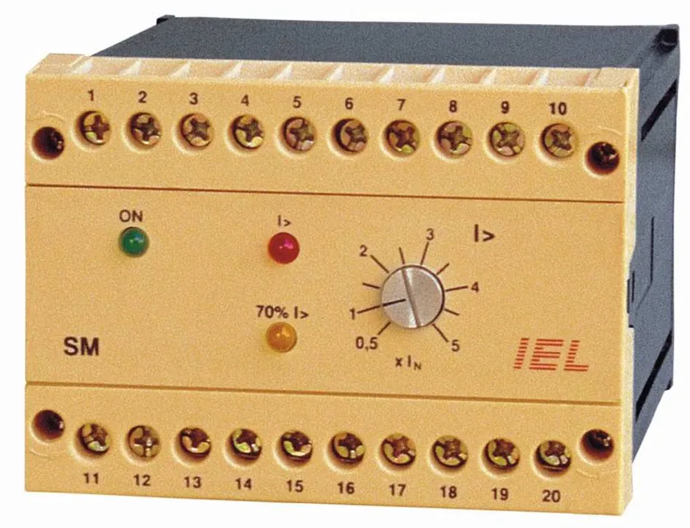
SM Current Module
Current module providing the current condition for ZELK-2/ZELK-3 devices and improving arc protection reliability.
The SM current module is used in arc protection systems to avoid false trips caused by light that is not produced by an arc. When busbar current exceeds the set value, the module provides the current condition required by ZELK-2 or ZELK-3. It also monitors the current decrease after tripping and provides a condition for breaker-failure protection.
-
Current condition for ZELK
A logic output enables ZELK-2/ZELK-3 operation when optical detection and current above the set threshold are both present.
-
Adjustable I> threshold
The operating current is adjustable from 0.5 to 5 x IN for 1 A or 5 A current-transformer secondaries.
-
Condition for ZPM
The 70% I> output is used for breaker-failure protection when current does not decrease after protection operation.
-
In-service testing
A test switch, TEST LED and potentiometer support checking the module and the complete protection system.
-
Availability supervision
Remote availability signalling is implemented with K1 relay and one changeover contact.
-
One-, two- or three-phase connection
Connection to current transformers is possible as one-phase, two-phase or three-phase.
- Rated current IN
- 1 A or 5 A
- Rated frequency
- 50/60 Hz
- Overload capacity
- continuous 5 IN; 1 s: 100 IN
- Input resistance
- 1 A input: 40 mOhm; 5 A input: 5 mOhm
- I> operating-current setting
- 0.5 - 5 IN
- Reset ratio
- 0.95
- Operating time
- < 7 ms at 1.2 I>; < 4 ms at 2 I>; < 1.2 ms at 10 I>
- Output for ZELK-2/ZELK-3
- open collector, 12 V / 120 mA
- Output for ZPM
- open collector, 12 V / 20 mA
- Input for SM
- galvanically isolated, 12 V / 20 mA
- Local signalling
- green power LED, red I> LED, yellow 70% I> LED
- Remote signalling
- module availability relay, 230 V AC / 300 V DC / 5 A, 1 changeover contact
- Supply voltage
- 230 V AC +10% / -20%; 24 V DC +10% / -20%
- Consumption
- max. 5 VA
- Temperature range
- -10...+55 °C
- Insulation
- 2.5 kV, 50 Hz, 1 min between all galvanically isolated circuits
- Mounting
- DIN EN 50022-35 rail or wall
- Dimensions
- 100 x 74 x 120 mm
- Terminals
- 2 x 2.5 mm2
Measurement inputs
Measuring system
Electronic outputs and inputs
Signalling
Power supply
General
- DIN EN 50022-35
- Insulation 2.5 kV, 50 Hz, 1 min
Related products